In brownfield refining, petrochemical, chemical, and offshore processing facilities, maintaining dedicated “inspection isometrics” represents one of the most resource-draining, error-prone overheads in Asset Integrity Management (AIM). For decades, plant operators have treated 2D Computer-Aided Design (CAD) piping isometric drawings as the mandatory medium for mapping Condition Monitoring Locations (CMLs), defining corrosion loops, and executing Risk-Based Inspection (RBI) workflows under API 570 and API 580/581.
However, as operating facilities undergo continuous Management of Change (MOC) cycles, minor revamps, and turnaround (TAR) modifications, specialized 2D drafting fails to keep pace. The result is chronic as-built drift, inflated drafting overhead, and dangerous documentation gaps in Process Safety Information (PSI).
Advances in mobile 3D reality capture and AI-driven spatial contextualization may have rendered manual isometric maintenance obsolete. By leveraging visual isolation within Shared Reality, process operators are transitioning to a reality-based inspection paradigm—substituting static 2D drawings with interactive, spatially isolated 3D digital twins linked directly to enterprise master data.
The As-Built Dilemma: The Hidden Tax of 2D Inspection Isometrics
Regulatory frameworks—including OSHA 29 CFR 1910.119 (Process Safety Management) and API 570 (Piping Inspection Code)—mandate rigorous documentation of physical piping systems, operational metallurgy, and inspection histories. Traditionally, inspection departments maintain secondary sets of drawings known as “inspection isometrics” or “sketch loops.”
These drawings serve three primary functions:
- Circuitization & Corrosion Loop Delineation: Grouping piping runs exposed to comparable process environments, operating temperatures, pressures, and Damage Mechanisms (DMs) per API 571.
- CML and TML Allocation: Pinpointing Thickness Measurement Locations (TMLs) for Non-Destructive Testing (NDT), such as Ultrasonic Testing (UT), Phased Array UT (PAUT), or Pulsed Eddy Current (PEC).
- Execution Packages: Providing field technicians and NDT contractors with spatial references to locate monitoring points on high-consequence lines.
Despite their ubiquity, 2D inspection isometrics impose severe operational bottlenecks:
- High Total Cost of Ownership (TCO): Updating a single CAD isometric drawing following an MOC requires site walkdowns, manual drafting, redlining approvals, and document management handoffs—costing hundreds of dollars per drawing revision.
- Spatial Disconnection: 2D orthographic and isometric projections do not convey surrounding physical congestion, structural steel, pipe racks, insulation cladding, or scaffolding access constraints.
- Siloed Inspection Data: CML coordinates sketched on 2D PDFs remain disconnected from the facility’s Computerized Maintenance Management System (CMMS) or Enterprise Asset Management (EAM) platform (e.g., SAP PM, IBM Maximo) and RBI calculation engines.
Enter Visual Isolation: The Mechanics of 3D Spatial Stripping
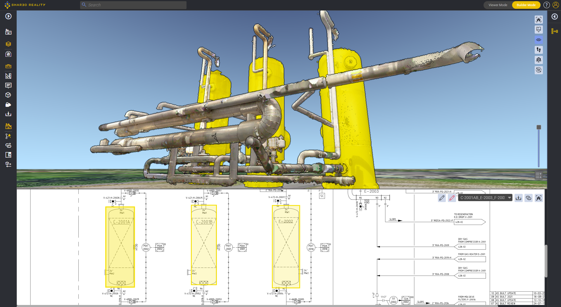
The Isolate Selection feature in Shared Reality directly replaces the need for specialized 2D isometric drafting. Powered by the Assetizer AI engine, which segments and classifies unstructured point clouds and 360° panoramic imagery into discrete 3D equipment classes, pipes, and structural elements, the platform allows users to strip away the surrounding plant environment instantly.
With a single click, an RBI engineer, materials specialist, or turnaround planner can isolate any arbitrary subset of the facility:
- A complete piping circuit spanning multiple elevations and process units.
- A specific corrosion loop comprising parent vessels, nozzles, run piping, bypass loops, and control valves.
- Individual equipment systems stripped of structural obstructions, cable trays, adjacent lines, and civil structures.
Once isolated, the targeted piping run exists as an interactive, dimensionally accurate 3D model. Teams can:
- Navigate from Any Angle: Pan, orbit, and zoom through complex manifold geometries without physical or visual obstructions.
- Extract Spatial Measurements: Accurately calculate pipe outer diameters, center-to-center run lengths, elevations, and clearances to nearby structures using native 3D measurement algorithms.
- Anchor Condition Monitoring Data: Embed persistent 3D annotations directly on the exact coordinates of inspection points, complete with inspection history logs, metallurgical reports, and ultrasonic thickness readouts.
Modernizing RBI and Corrosion Loop Management (API 580/581 & API 570)
Connecting spatial isolation with Shared Reality’s integrated 3D Business Intelligence (3D BI) and unified 1D-2D-3D data model elevates Risk-Based Inspection programs from static spreadsheets to dynamic visual workflows.
- Visual Circuitization and Damage Mechanism Mapping
Corrosion loops require grouping components subjected to identical corrosive operating environments (e.g., wet , high-temperature sulfidation, amine service, or naphthenic acid corrosion) and defined Integrity Operating Windows (IOWs). Rather than manually highlighting lines across disparate 2D drawings, engineers can select the entire circuit in Shared Reality, isolate it, and verify boundary isolation valves, drain legs, dead-legs, and injection points in true spatial context.
- High-Precision CML / TML Placement
Corrosion Under Insulation (CUI), Flow-Accelerated Corrosion (FAC), erosion at change-of-direction fittings, and dead-leg pitting do not occur uniformly. Placing CMLs on 2D isometric sketches routinely leads to field location errors. In Shared Reality, CMLs are placed directly onto the digital surface of the asset as 3D annotations. Field NDT technicians can open the digital twin on an intrinsically safe tablet, locate the exact point of interest relative to structural landmarks, and record thickness readings without ambiguity.
- Criticality Colorization via 3D Business Intelligence (3D BI)
Through Shared Reality’s 3D BI engine, equipment and piping lines can be dynamically color-coded based on metadata ingested from CMMS/EAM or RBI software (e.g., Meridium, Credo, Visions):
- Risk Matrix (PoF CoF): Color-code lines by Probability of Failure (PoF) and Consequence of Failure (CoF) to immediately highlight high-risk circuits requiring imminent shut-down inspection.
- Corrosion Rate & Wall Thinning: Colorize circuits by calculated corrosion rate ( or ) or remaining life threshold ( years in red, years in yellow, years in green).
- Compliance & Scheduling: Filter the isolated circuit by “Next Inspection Date” or “Overdue NDT Work Orders” to streamline Turnaround (TAR) scope definition.
2D CAD Isometrics vs. Reality-Based 3D Digital Twins
The operational advantages of transitioning from drafting-centric deliverables to an AI-driven, reality-based methodology are concrete across all asset lifecycle dimensions:
Functional Metric | Traditional 2D Inspection Isometrics | Shared Reality (Isolate Selection + 3D BI) |
Data Capture & Authoring | Labor-intensive site walkdowns; manual CAD drafting from scratch ($150–$400+ per spool). | Rapid terrestrial laser scanning (TLS) or mobile SLAM; automated point cloud segmentation via AI Assetizer. |
MOC / As-Built Alignment | Prone to drawing backlog; documentation lags physical field modifications by months or years. | Continuous Source of Truth: localized updates via 3DSync/local scanning update the twin within hours. |
Spatial Context & Accessibility | Flat representation; omits adjacent physical clashes, structural steel, and elevation obstacles. | True 3D coordinate model; full visual inspection from any orbital vector with background stripping. |
CML / TML Traceability | Approximate dot annotations on schematic lines; high risk of field technician misinterpretation. | Centimeter-accurate 3D spatial pins containing attached inspection logs, photos, and NDT thickness logs. |
PSM / LOTO Preparation | Multi-sheet cross-referencing between P&IDs, PFDs, and piping isometrics to identify isolation blinds. | Instant line tracing from source to terminus; clear visibility of spectacle flanges, bleeder valves, and block valves. |
Scaffolding & Rigging Planning | Requires pre-inspection field visits to estimate scaffolding heights and crane pick radiuses. | Direct spatial measurements of clearance, floor-to-pipe elevation, and adjacent interference in 3D. |
Operational Synergies: PSM, Turnarounds (TAR), and LOTO Isolation
Beyond baseline RBI compliance, isolating piping selections yields substantial cross-functional efficiencies:
Lock-Out / Tag-Out (LOTO) & Turnaround Isolation
During turnaround execution, isolating process equipment for safe entry requires positive physical isolation (blinding, double block and bleed). Using Isolate Selection, turnaround planners can trace an entire hydrotreater circuit or boiler feed line, identify all boundary valves, bypass connections, and bleeder valves, and export an isolated 3D view directly into the isolation work package. This eliminates line-tracing walkdown errors, mitigates hazardous chemical releases, and speeds up plant depressurization and purging.
Contractor Enablement and Bid Scoping
Third-party inspection and scaffolding contractors often spend up to 30% of their billable hours walking units to scope jobs and verify drawing accuracy. Providing contractors with secure, scope-restricted access to isolated 3D systems allows them to estimate scaffolding requirements, compute insulation removal surface areas, and plan radiation perimeters (for radiographic testing) remotely.
Synchronized 2D-3D Redlining
When physical inspections reveal discrepancies—such as an undocumented bypass spool or a retired valve that remains on the P&ID—Shared Reality’s unified environment allows builders to redline the 2D schematic while maintaining direct links to the isolated 3D point cloud. Discrepancies are logged in real time, upholding Process Safety Information (PSI) integrity under OSHA PSM requirements without waiting for formal CAD drafting turnarounds.
Why Reality Capture Outperforms CAD Maintenance
Process facilities are dynamic industrial ecosystems. Maintaining a dual ecosystem of 3D CAD design models, 2D P&IDs, and specialized 2D inspection isometrics requires an unsustainable investment in drafting overhead. As high-speed terrestrial laser scanners (TLS), handheld mobile SLAM systems, and high-resolution 360° cameras become commoditized on-site tools, the unit economics of data capture have permanently inverted:
Capturing a million square feet of accurate, photorealistic 3D point cloud data is now faster and significantly less expensive than manually updating and drafting 100 piping isometric drawings.
By extracting intelligence directly from reality data through AI-based segmentation and the Isolate Selection tool, samp.ai eliminates the drafting bottleneck. Asset Integrity and RBI teams regain full ownership of their physical assets—anchoring corrosion loops, CMLs, and process safety barriers to the single undisputed authority: the physical reality of the plant.
To see the “Isolate Selection” feature in action and learn how forward-thinking operators are modernizing their RBI and corrosion management programs, register for the upcoming technical webinar: Stop Maintaining Your Isometric Drawings: A Reality-Based Approach to Corrosion, Isolation, and Inspection Management.