Transforming Brownfield Process Facilities from Static 3D Scans to Semantic Digital Twins
In brownfield refining, petrochemical, chemical processing, and utility plants, technical documentation rarely matches physical reality. Decades of operational modifications, debottlenecking projects, and minor revamps carried out under rapid Management of Change (MOC) cycles create a compounding rift between 1D asset registers in Computerized Maintenance Management Systems (CMMS) or Enterprise Asset Management (EAM) platforms (e.g., SAP PM, IBM Maximo), 2D Piping and Instrumentation Diagrams (P&IDs), and the physical as-built facility.
Resolving this documentation deficit has historically required capital-intensive engineering audits, physical site walkdowns, and manual drafting updates. While reality capture technologies have surged across industrial operations, capturing the plant is no longer the bottleneck. The acute bottleneck is converting raw visual and spatial point data into contextualized, auditable engineering intelligence.
Through automated spatial tagging—powered by in-scan Optical Character Recognition (OCR) embedded within Shared Reality and its Assetizer AI engine—operators can now extract physical label data directly from 360° panoramic imagery embedded in 3D scans. By anchoring physical plant labels directly to CMMS tags and 3D geometries without requiring an existing, validated P&ID as an intermediary, industrial operators can rapidly turn monolithic scans into interactive digital twins, streamline turnaround (TAR) preparations, and unlock comprehensive line-by-line P&ID validation via automated pipe crawling.
1. The Brownfield Digitization Paradox: The Mobile SLAM Influx
Reality capture in the process industries has reached an inflection point driven by the commoditization of Terrestrial Laser Scanning (TLS) and mobile Simultaneous Localization and Mapping (SLAM) systems. Handheld, backpack, and drone-mounted mobile SLAM devices, paired with high-resolution 360° spherical camera rigs, enable field crews to capture hundreds of thousands of square meters in days rather than months. As scanning hardware has become accessible to casual users and non-specialist field teams, industrial facilities are capturing more 3D spatial and optical data than ever before.
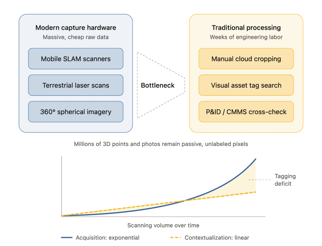
This capture democratization has exposed an operational paradox: data acquisition is now exponential, but data contextualization remains linear and manual.
A raw 3D point cloud—whether formatted as .e57, .las, or .laz—is fundamentally a collection of spatial coordinates () and RGB color values. It possesses no native awareness of whether a cluster of points represents an API 610 centrifugal pump, an ASME B16.5 pipe flange, or an inert structural steel column. Similarly, embedded 360° panoramic images traditionally function as passive “street views” for remote viewing rather than structured datasets.
To make this spatial data useful for downstream use cases—such as Asset Integrity Management (AIM), Risk-Based Inspection (RBI), Process Safety Management (PSM), or Turnaround planning—engineers have historically had to manually navigate the point cloud, find equipment tags, cross-reference them with printed P&IDs or CMMS tables, and hand-draw digital bounding boxes. When P&IDs are out of date or missing, the process stalls entirely.
As scanning volume accelerates, the manual tagging deficit compounds. Brownfield operations require an automated, reality-first bridge that converts raw visual and spatial data into an intelligent, semantic operational model without manual engineering overhead.
2. Technological Core: In-Scan 360° OCR via the Assetizer AI Engine
The foundational technology resolving this ingestion bottleneck is the expanded Assetizer AI Engine within the Shared Reality workspace.
Assetizer operates via a dual-vector architecture:
- 3D Geometric Classification: Segmenting dense point clouds into discrete geometric clusters and assigning cross-industry asset classes (e.g., vessels, pumps, control valves, check valves, dismantling joints).
- 2D/Optical Intelligence: Parsing high-resolution 360° equirectangular panoramic photographs registered within the 3D point cloud coordinate system.
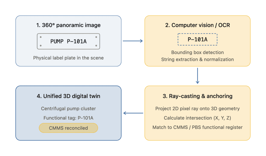
The Spatial OCR Mechanics
When a reality capture package is uploaded (such as structured E57 files containing embedded panoramic scanner stations), Assetizer identifies the spatial origins of every 360° photo bubble. As the computer vision pipeline ingests the spherical imagery, it executes Optical Character Recognition focused specifically on physical plant identification markers:
- Stamped stainless steel/brass equipment nameplates.
- Stenciled pipe service labels and flow-direction arrows.
- Stamped valve inspection tags and wire-hung maintenance discs.
- Electrical cabinet, junction box, and skid identifiers.
Once text is extracted, the platform applies ray-casting algorithms that project outward from the optical center of the 360° camera through the 2D bounding box of the detected label into the surrounding 3D point cloud. By computing the exact geometric intersection with the scanned surface, the system calculates the real-world spatial coordinate () of the label.
Reconciliation with Master Data (PBS / CMMS)
Extracted alphanumeric strings are immediately compared against the facility’s uploaded Plant Breakdown Structure (PBS) or CMMS equipment register. Industrial environments present real-world obstacles: labels suffer from chemical corrosion, paint overspray, atmospheric weathering, or partial shadowing.
To overcome surface degradation, Assetizer deploys error-management and fuzzy-matching logic. If an OCR extraction reads “IL-101A” due to a scratched character on a stainless plate, the algorithm reconciles the reading against the CMMS reference tag “11-101A”. Matches within acceptable confidence thresholds are automatically mapped, while larger discrepancies are isolated as candidate tags for human verification.
3. Human-in-the-Loop Governance: 100% Auditability for Critical Operations
In high-hazard environments governed by regulatory regimes such as OSHA 29 CFR 1910.119 (Process Safety Management) or the European Seveso III Directive (Directive 2012/18/EU), fully autonomous AI systems without deterministic oversight are unacceptable. Operating licenses require complete traceability for every asset modification and Process Safety Information (PSI) update.
Shared Reality enforces a strict “AI Proposes, Human Validates” workflow. Automated spatial tagging does not arbitrarily overwrite engineering records; it acts as an intelligent assistant that surfaces candidate linkages for rapid engineering authorization.
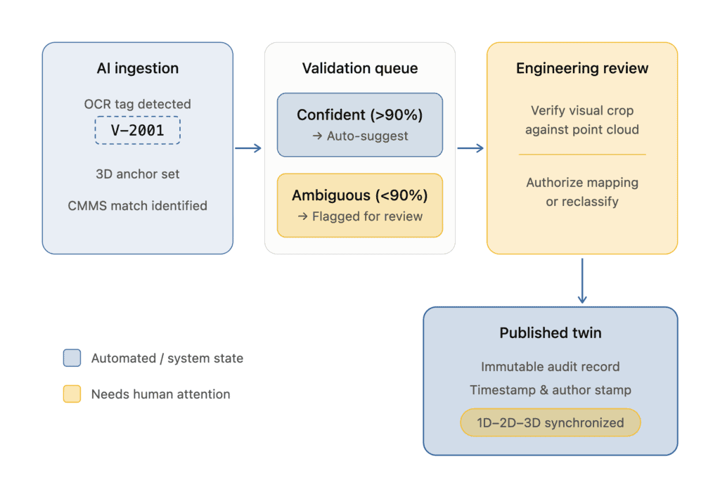
The Validation Workflow in Builder Mode
1. Candidate Staging: Assets identified via 360° OCR are staged inside the Builder Mode workspace. The interface displays the 3D model alongside a contextual crop of the original 360° photo showing the physical label.
2. Deterministic Verification: The builder reviews the proposed match between the segmented 3D physical object and the 1D CMMS entry. With a single click, the user validates the suggestion, remaps it, or assigns it as an unlinked specialty tag.
3. Traceability Logging: Every confirmed spatial tag records an immutable digital footprint: author ID, validation timestamp.
4. Publishing Controls: Staged data remains isolated in Builder Mode until an authorized administrator verifies the quality assessment, publishing the verified model to standard Viewers across the enterprise.
4. Transforming Monolithic Scans into Semantic Reality Models
Once physical labels are converted into spatial anchors, the facility scan transitions from a passive geometric record into a semantic 3D reality model. Every classified component becomes an active, interactive entity wired directly into the plant’s broader data architecture.
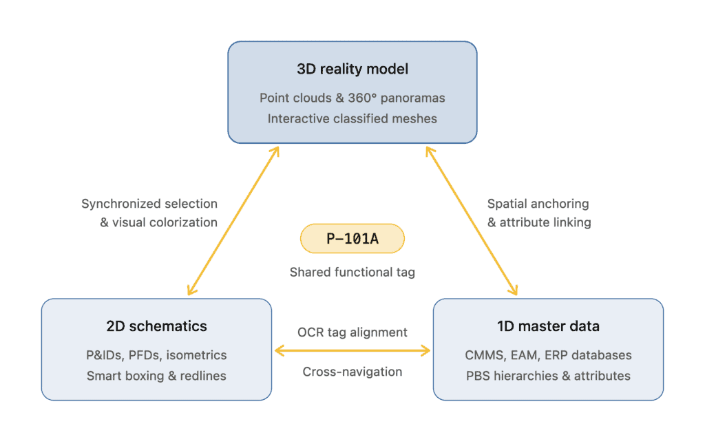
Tri-Directional Synchrony (1D-2D-3D)
In Shared Reality, spatial tagging establishes bi-directional and tri-directional synchronization across the operational representations of the plant:
- 3D Reality: Point clouds and 360° panoramic views providing geometric fidelity.
- 2D Schematics: Piping and Instrumentation Diagrams providing functional process logic.
- 1D Metadata: CMMS asset registers, maintenance records, and equipment hierarchies providing business context.
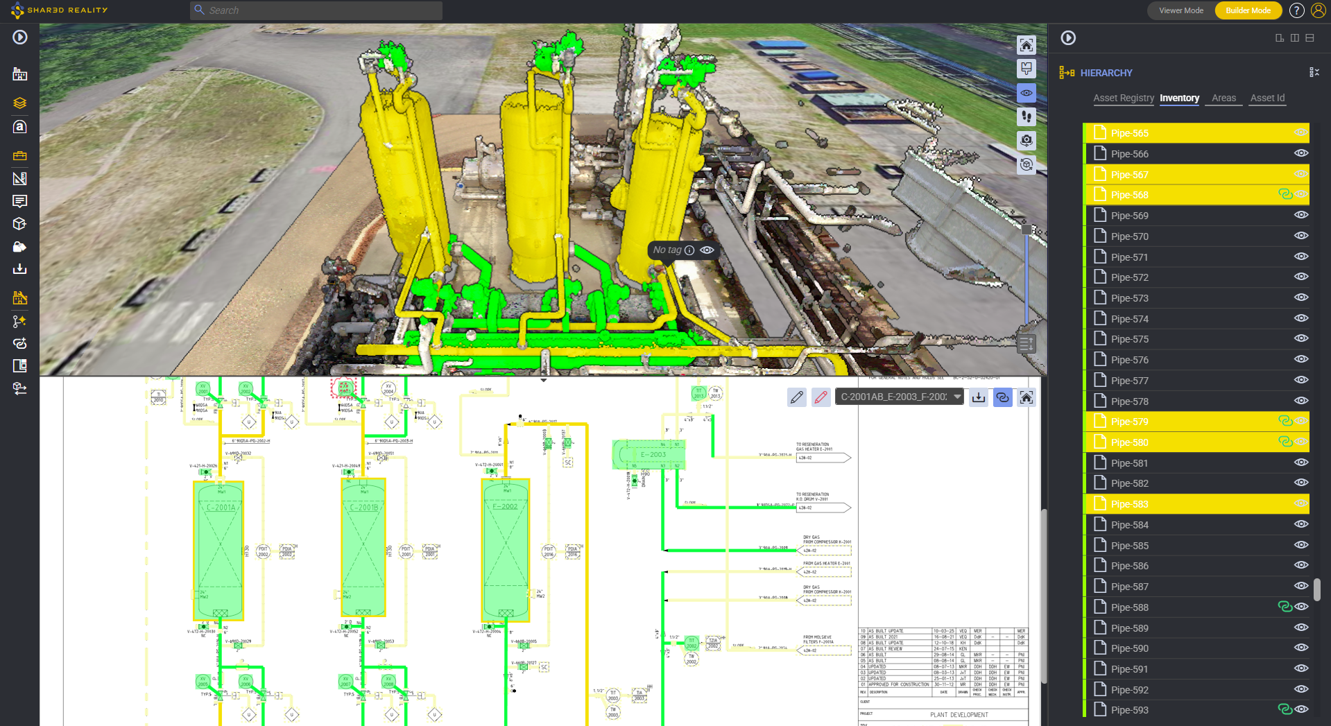
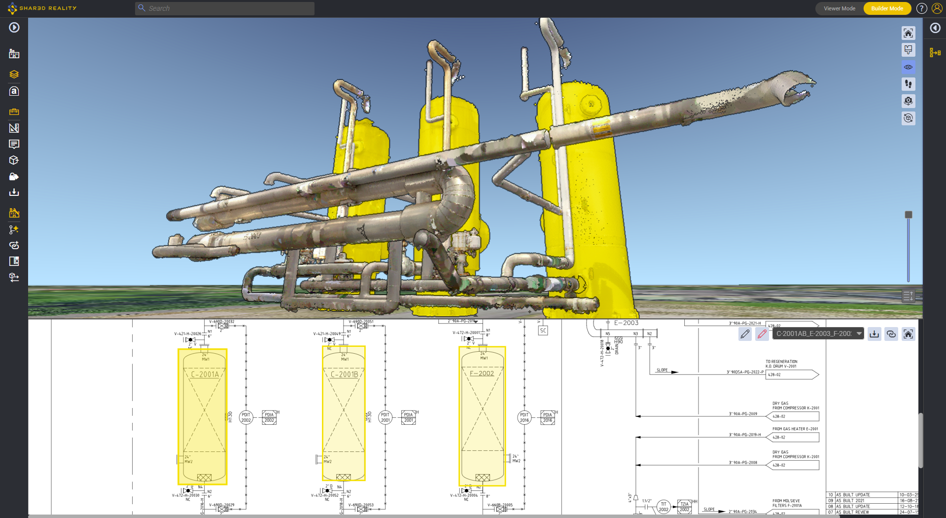
Selecting a tagged control valve in the 3D point cloud instantly commands the viewer to open its linked 1D CMMS maintenance history and automatically center, highlight, and zoom to that exact valve on the relevant 2D P&ID sheet.
Conversely, searching for an equipment tag in the CMMS bar immediately flies the 3D camera to its real-world physical coordinates in the plant, highlighting its geometry via 3DGlow.
3D Business Intelligence (3D BI) Activation
Converting raw geometry into semantic assets unlocks 3D Business Intelligence (3D BI). Rather than navigating external tabular databases, engineers can dynamically colorize the 3D plant based on real-time operational attributes:
- Reliability & Maintenance Status: Highlighting equipment with overdue preventative maintenance work orders, active backlog notifications, or high criticality ratings.
- Asset Integrity & Corrosion Management: Visualizing piping circuits based on remaining wall thickness, calculated corrosion rates, or Integrity Operating Window (IOW) exceedances.
- Process Safety & Operations: Displaying operating temperatures, design pressures, or Management of Change review statuses across units.
5. Granular Verification: Accelerating P&ID Validation and “Pipe Crawling”
On mature brownfield sites, up to 30% of P&IDs contain physical discrepancies—ranging from abandoned piping legs and undocumented tie-ins to reversed check valves and missing spectacle blinds. However, launching a comprehensive P&ID revalidation initiative is notoriously difficult because engineers lack verified starting baselines in the field.
Automated spatial tagging solves this “where to begin” problem. By automatically locking major equipment (pumps, exchangers, vessels, actuated valves) to their real-world 3D coordinates from visible labels, the platform establishes an immovable grid of spatial seeding points.
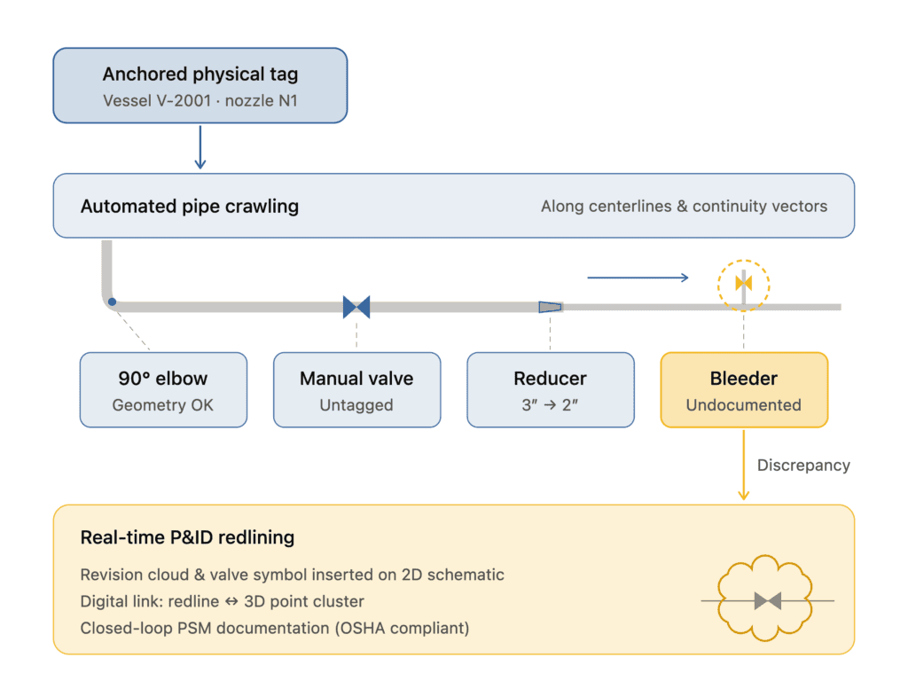
The Mechanics of P&ID Validator
In most process plant, more than 70% of equipment and piping components carry no individual CMMS tag. Manual block valves, bypass lines, bleeder assemblies, sample points, and instrument tees are rarely barcoded or stamped with functional identifiers. Traditional OCR cannot solve this untagged volume because there is no physical label to read.
This is where pipe crawling takes over thanks to the P&ID Validator:
- Seeding: The algorithm begins at an anchored physical asset identified via 360° OCR (e.g., Discharge Nozzle on Pump P-101A).
- Topological Traversal: Guided by Assetizer’s segmentation and classification of the 3D scan and P&ID, the system crawls along the connected pipe run.
- In-Line Asset Detection: As the algorithm crawls through space, it detects connectivity corresponding to in-line fittings: flanges, elbows, tees, manual hand valves, and reducer spools.
- Schematic Sequence Matching: The sequence of detected inline shapes is correlated directly against the topological sequence on the corresponding 2D P&ID.
When the P&ID Validator algorithm encounters an inline valve or a tie-in branch in the 3D scan that does not exist on the P&ID, the system flags an immediate as-built discrepancy.
Engineers can then activate P&ID Redlining directly inside the platform, sketch the undocumented component, link the new 2D graphic to the 3D point cluster, and export an auditable engineering package (PDF/PNG) to update the facility’s master drawings.
6. Business Value & Operational ROI Across the Asset Lifecycle
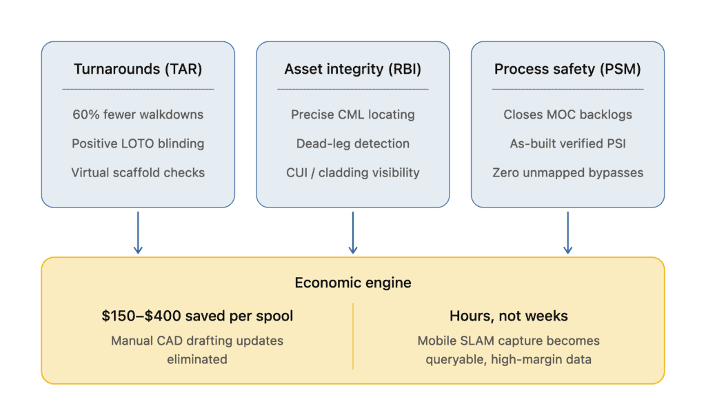
Implementing reality-first automated spatial tagging fundamentally shifts the unit economics of brownfield asset management across several operational domains:
6.1 – Turnaround (TAR) & Revamp Optimization
Turnaround planning typically requires months of preliminary field walkdowns by internal planners and external contractors to scope mechanical work, locate blind flange locations, and plan crane rigging.
- Virtual Job Packaging: Planners isolate systems remotely, verify valve packing access, and confirm positive isolation points (double block and bleed) without entering hazardous operating units.
- Scaffolding Rework Mitigation: Using spatial measurement and 3D shape simulation tools, planners model scaffolding footprints virtually against the as-built scan, cutting field scaffolding modifications by up to 30%.
6.2 – Risk-Based Inspection (RBI) & Non-Destructive Testing (NDT)
Under API 570 and API 580/581 programs, locating Condition Monitoring Locations (CMLs) and Thickness Measurement Locations (TMLs) on paper isometrics leads to field measurement drift.
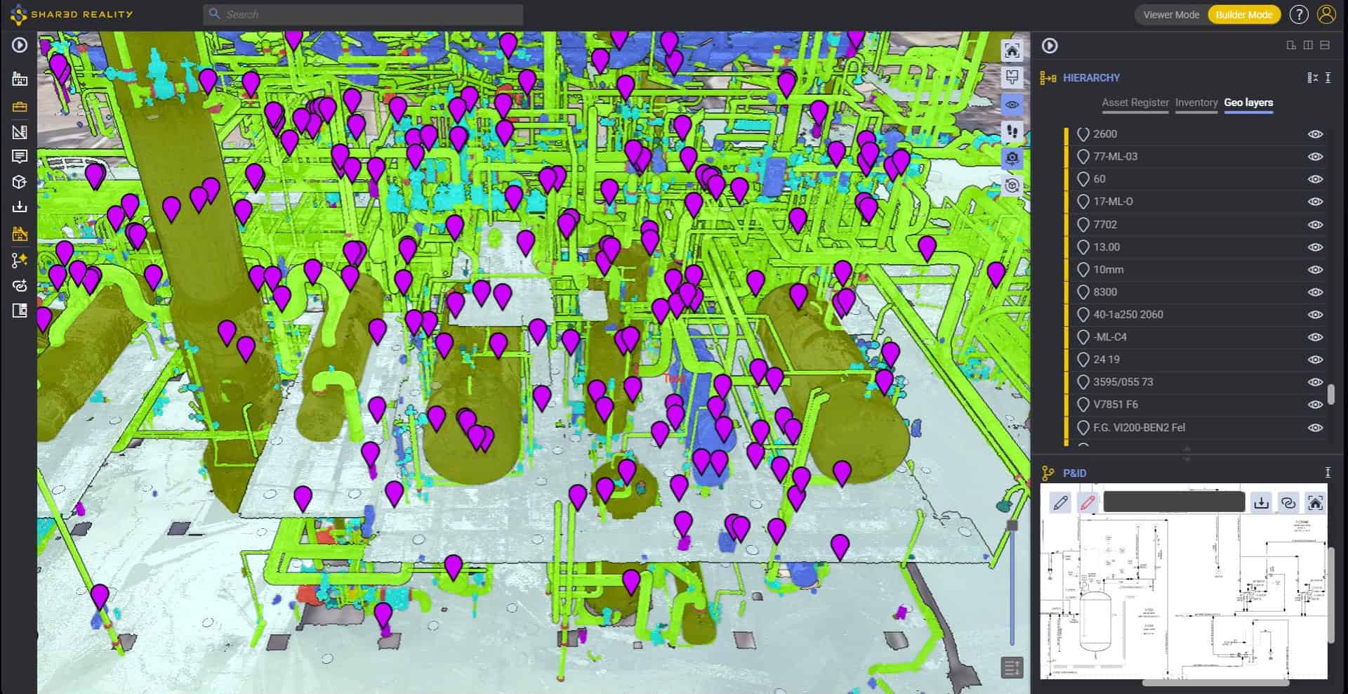
- Sub-Centimeter CML Precision: Inspection points are pinned via 3D Annotations directly to the physical pipe extrados or nozzle neck in 3D space.
- Elimination of NDT Search Overhead: Field technicians access the twin via intrinsically safe tablets, navigate directly to the specified CML coordinate using visual 3D landmarks, and review historical ultrasonic thickness logs on-site.
6.3 – EAM/CMMS Data Integrity & Master Data Governance
Mergers, acquisitions, and legacy plant operations frequently leave CMMS databases corrupted with “ghost assets” (records for retired equipment that no longer physically exist) and unmapped field additions.
- Automated Reconciliation: Running in-scan OCR across the entire plant reconciles physical inventory against the CMMS database, generating an auditable inventory report showing unmapped physical assets versus orphan database entries.
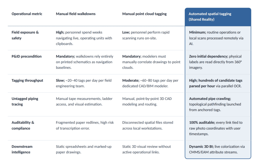
7. Comparative Analysis: Evolution of Industrial Tagging
The transition from physical field surveys to automated spatial tagging represents a dramatic leap in engineering throughput and safety performance:
8. Strategic Adoption: Scaling from Scan Ingestion to Operational Truth
Deploying automated spatial tagging does not require a disruptive overhaul of existing enterprise software. It acts as an agile contextualization layer sitting between physical reality and enterprise master data.
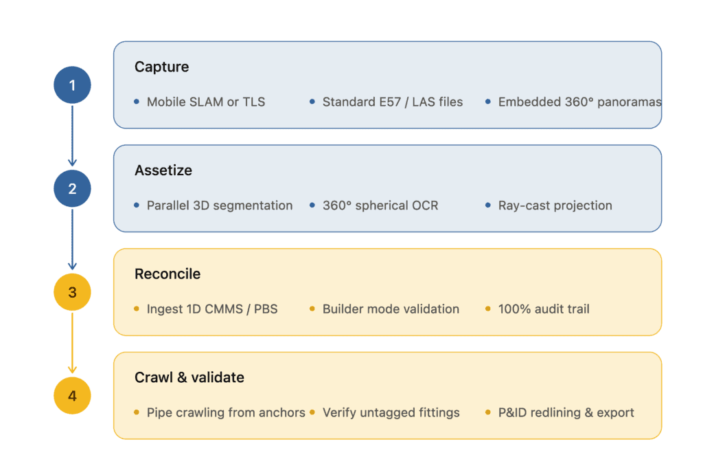
Industrial plant operators can implement this capability through four structured steps:
- Ingest Existing Reality Data: Upload existing or newly acquired terrestrial laser scans or mobile SLAM datasets containing registered 360° panoramic imagery.
- Execute Assetizer Multi-Modal AI: Run the automated processing pipeline to classify 3D geometries and parse embedded 360° optical imagery for physical label detection.
- Validate Spatial Anchors: Using the collaborative Builder Mode, engineering teams review AI candidate matches against the CMMS register, establishing an authenticated baseline of spatial anchors.
- Deploy Pipe Crawling & P&ID Validation: Launch topological pipe crawling from validated equipment nozzles to map untagged piping spools, identify as-built field discrepancies, and export verified engineering packages.
By decoupling plant digitization from slow, manual CAD drafting and grounding asset registers directly in physical reality, brownfield operators can finally eliminate the reality-data gap—turning passive point clouds into intelligent, connected digital twins that safeguard process integrity and operational profitability.